OpticStudio provides various design tools for common surface structures, scatter profiles, beam definitions, etc. some simulations require custom definitions. The most flexible option for defining custom optical properties is a user-defined DLL. Why Anatoli Trafimuk uses user-defined objects for design our non-imaging optics:
- They provide a built-in fully integrated, simple solution for efficient design of freeform based illumination system in non-sequential mode.
- Use simplified Bezier curves (up to 4) to create surfaces and solid objects
- User-defined objects are an easy way to describe the lenses based on Bezier curves.
- UDO behaves like a built-in object, has a fast raytrace, and fully integrated into optimization.
What was done by Anatoli Trafimuk:
- Created 20+ freeform UDO to describe illumination systems natively in Zemax. All DLLs was written with Microsoft Visual Studio software
- All UDO has parameters for optimization its shape, control the geometry, size, and special features like faceting, fillets, etc.
- Created a set of ZPL macro which allows scaling the UDO, change their parameters, change surface properties, control the slope, control the shape, and much more.
- Also, there are several macros to create a direct CNC machine command file for some types of UDO.
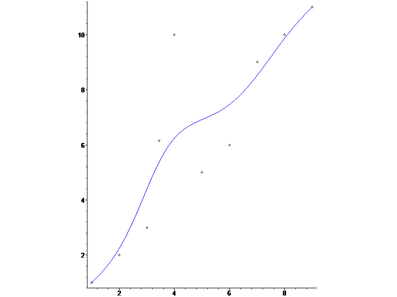
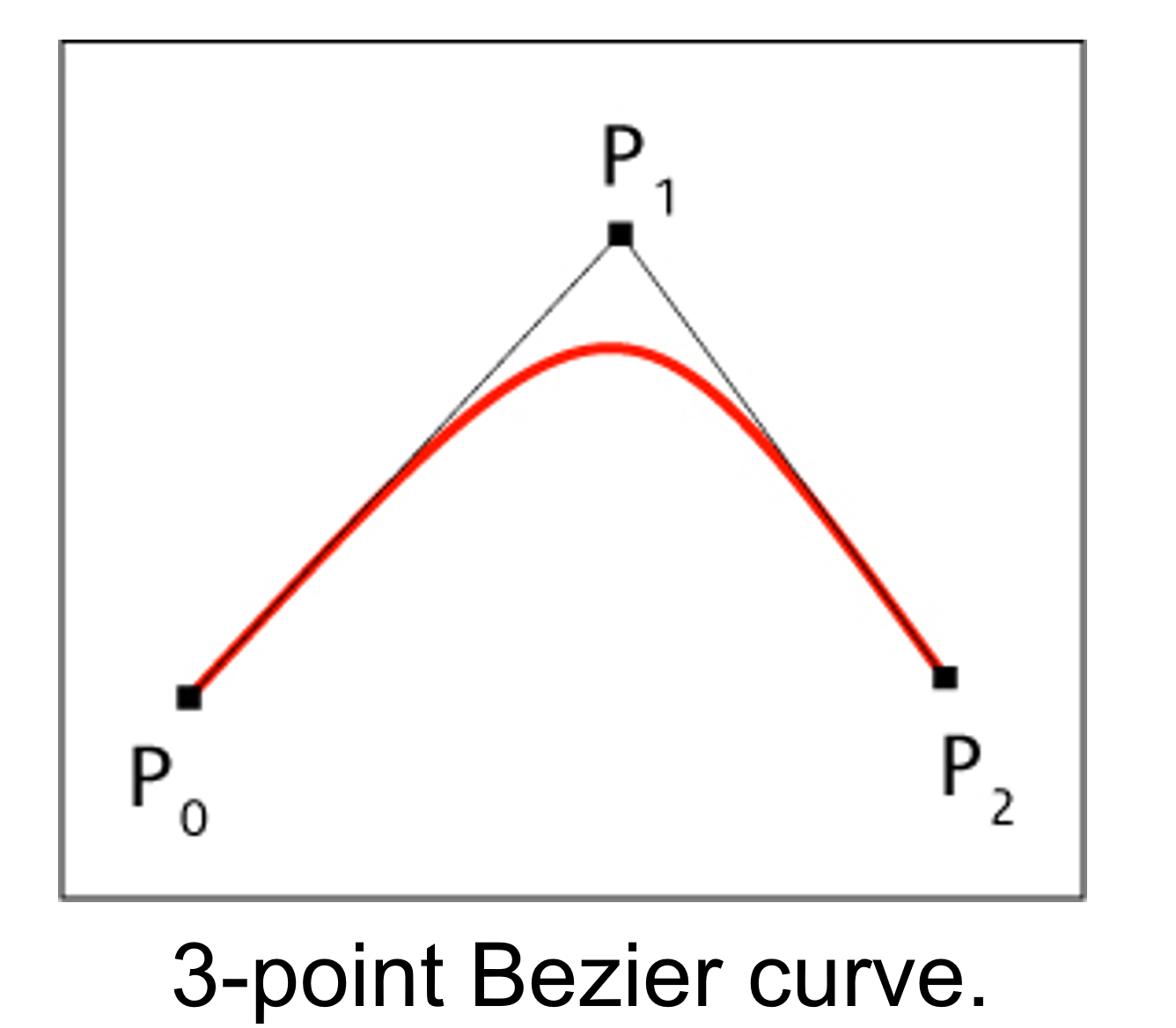
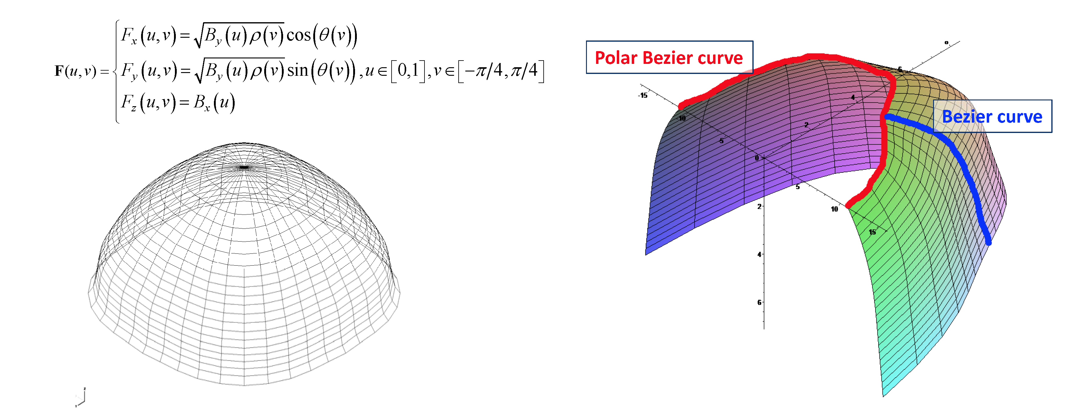
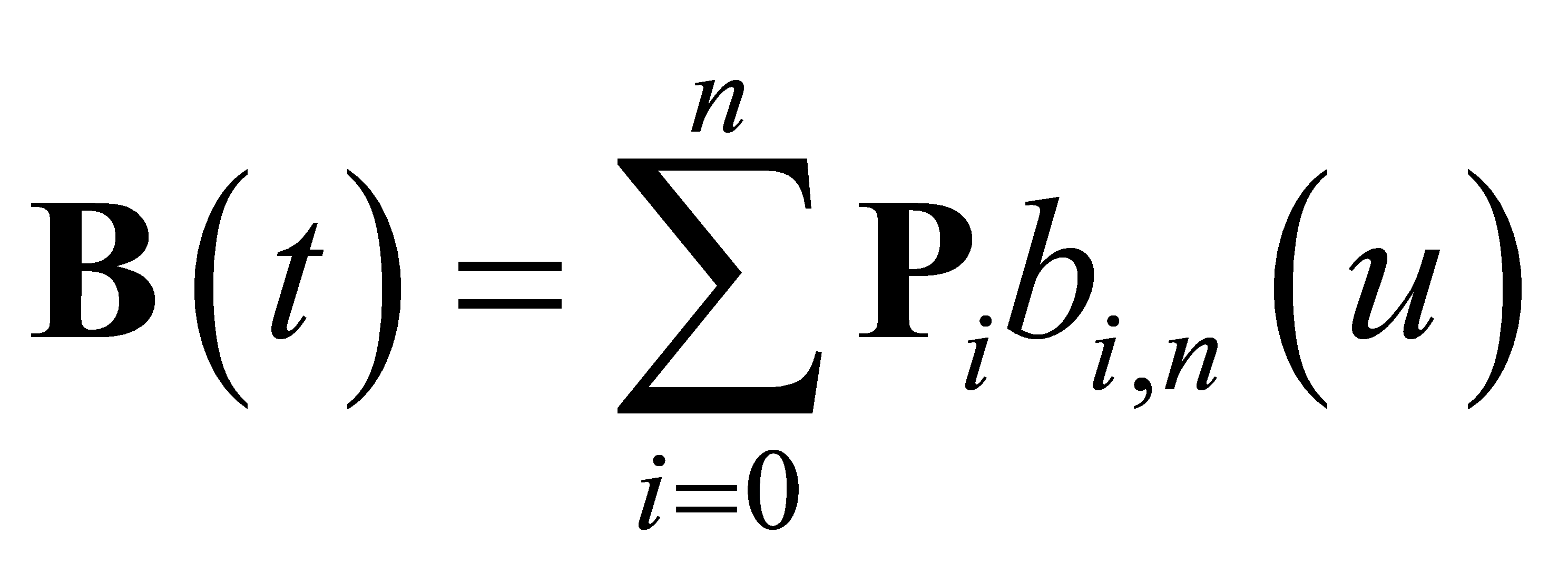
To creating UDO in Zemax Anatoli Trafimuk uses Bezier curves. Bezier curve is a parametric curve used in computer graphics and related fields. The curve, which is related to the Bernstein polynomial, is named after Pierre Bezier, who used it in the 1960s for designing curves for the bodywork of Renault cars. Other uses include the design of computer fonts and animation. The curve is simple to use. It controlled by control points set, which are just a set of numbers. Point not lie on the curve except start and end point. This is best to build freeform optical surfaces.
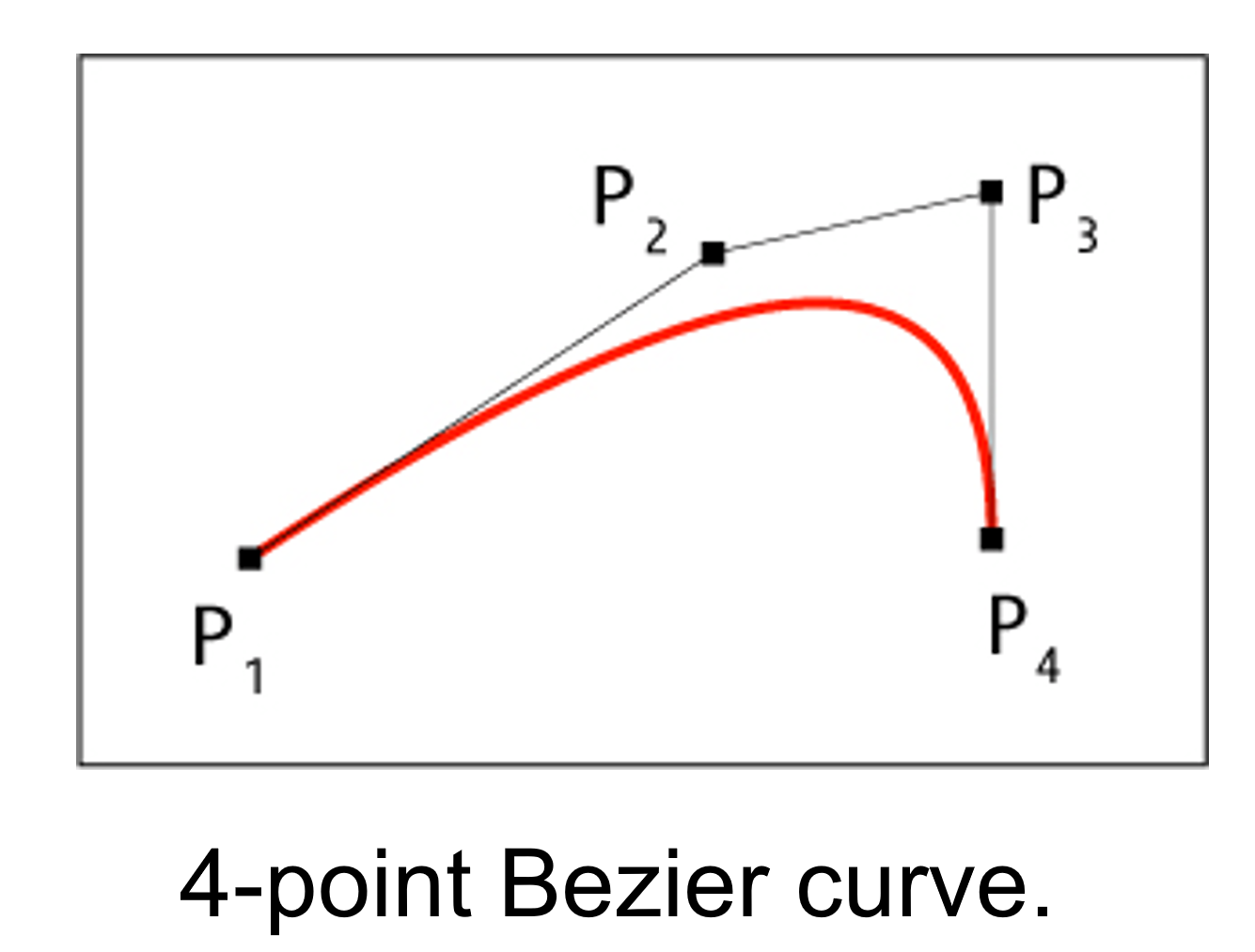
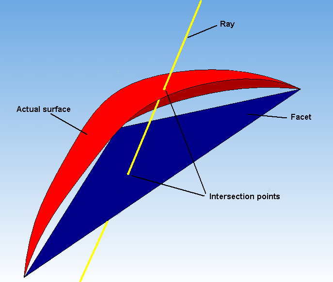
The simplified Bezier curve used for creating objects. The feature of that curve representation is that X control points equally spaced along the axis. So we use the only parametrization of the Y part of the curve. This allows us more simple calculations while creating complex objects from those curves. The raytrace for surfaces based on that curve is 30% faster rather than usual Bezier curves and up to 60% faster if use more general NURB representation.
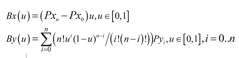
And we remain almost all flexibility of freeform and use fewer variables. The equation of the simplified Bezier curve is the following:
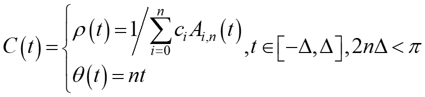
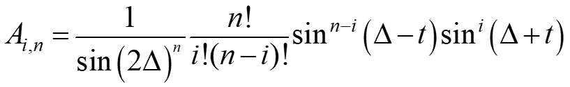
And its polar form is the following:
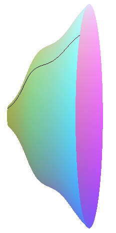
Some important surfaces created from Bezier curves
- 3 Surface of revolution of simplified Bezier curve ( TIR)
- The surface of revolution of simplified Bezier curve along simplified polar Bezier curve ( Type V beam shaping)
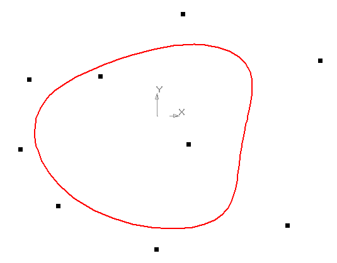
- The surface of the revolution of 4 simplified Bezier curve along a simplified polar Bezier curve. Each independent curve describes the quarter of the 360-degree surface. Curves use the same X parametrization while Y is different.
- Extrude the simplified Bezier curve along another simplified Bezier curve
To create the UDO we need use 3 steps:
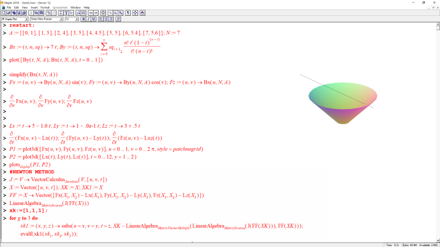
Step 1. Model surface equations in math software, e.g. free version of MapleV5
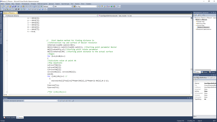
Step 2: Create C++ code for surface shape and raytracing and compile it into DLL
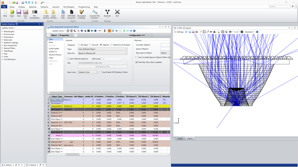
Step 3: Import Dll in Zemax as User Defined Object
Several examples of the most commonly used objects are shown below.
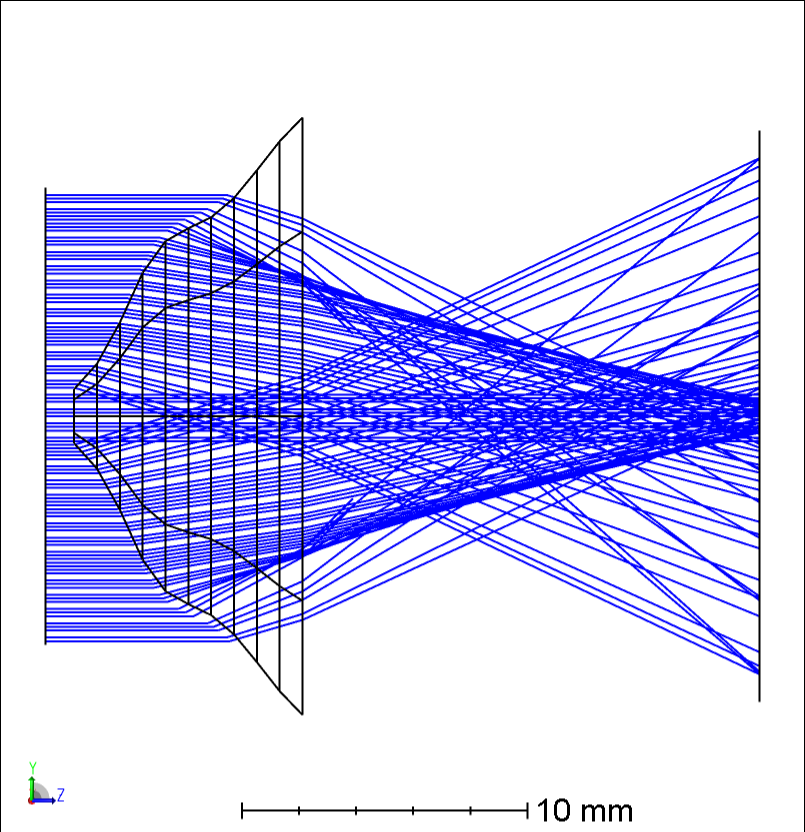
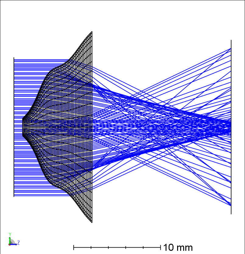
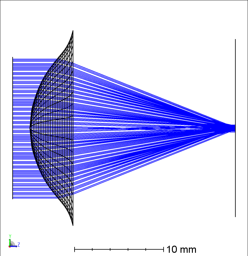
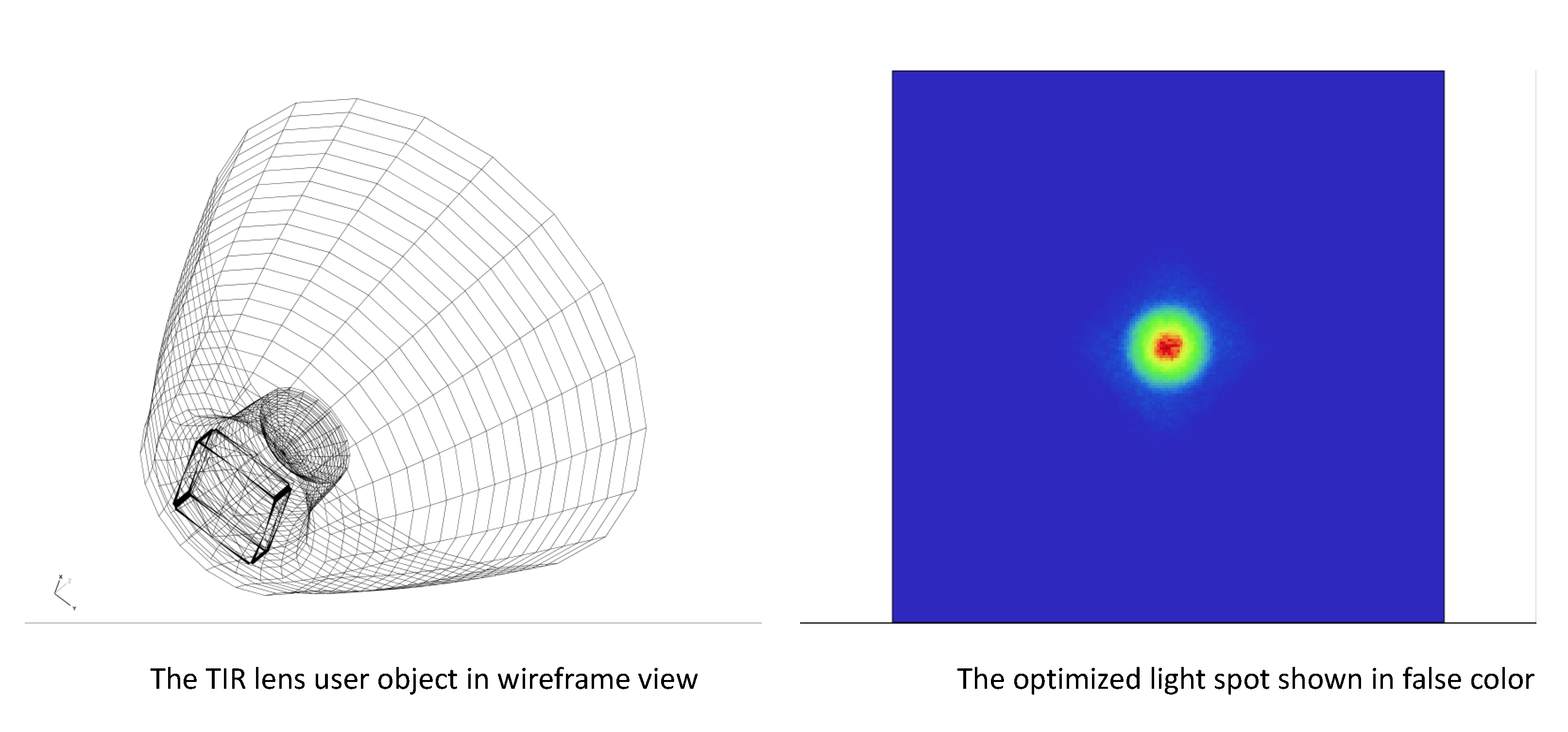
1. TIR lens designed with UDO in Zemax Optics Studio
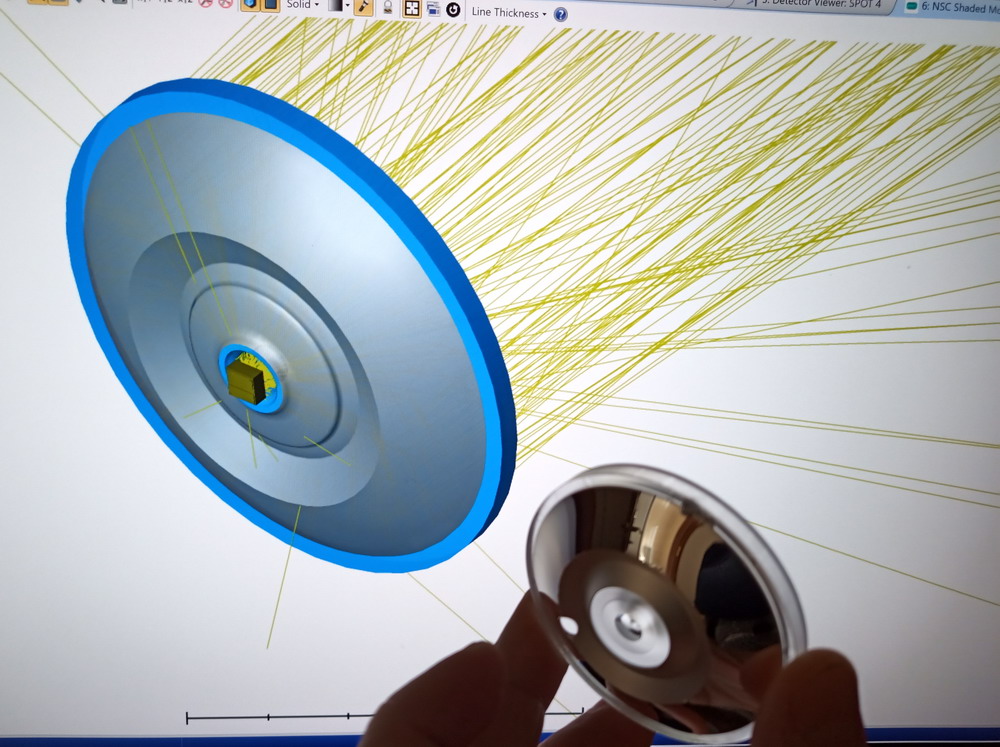
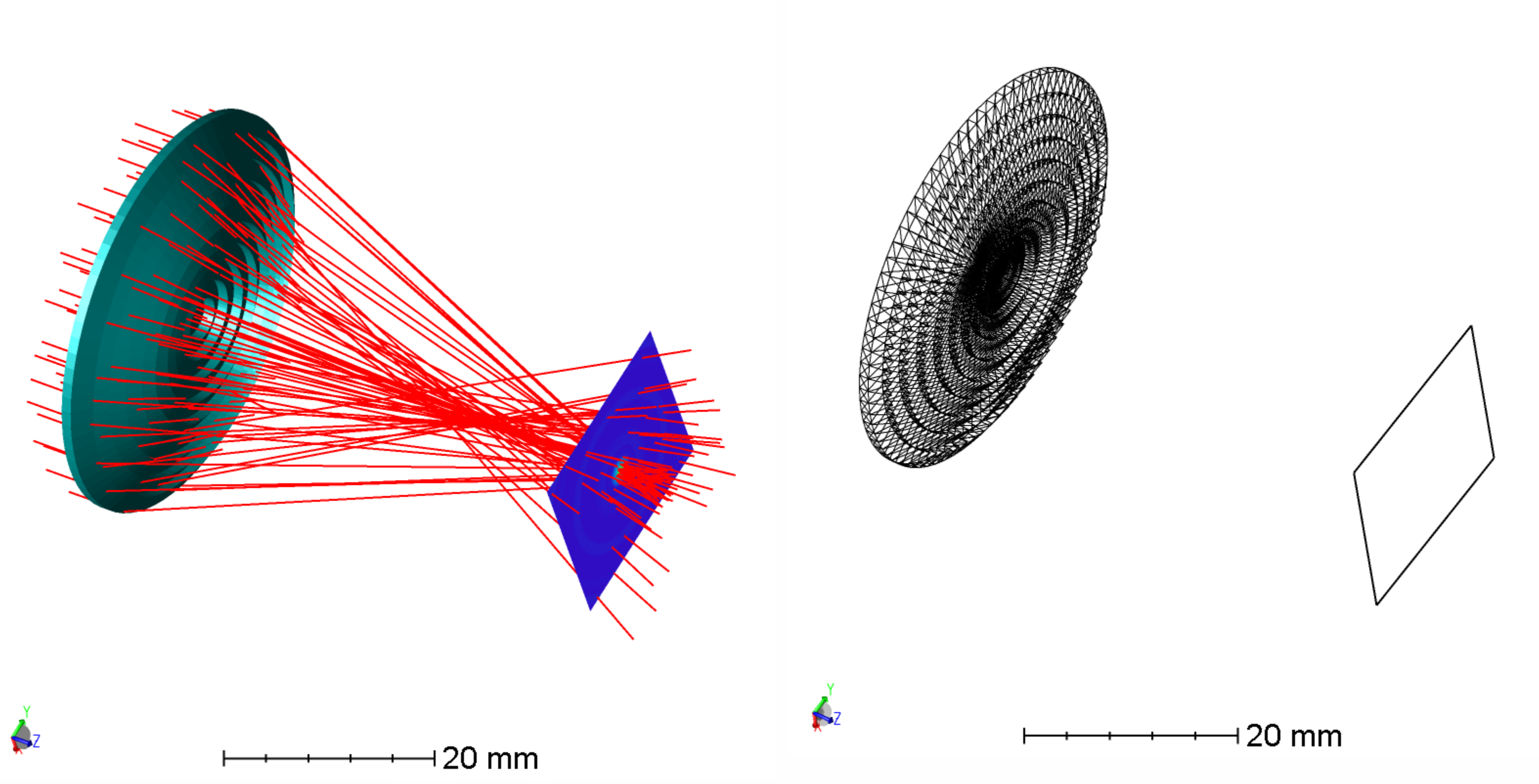
2. Example of surface of revolution of Bezier curve along the polar Bezier curve:
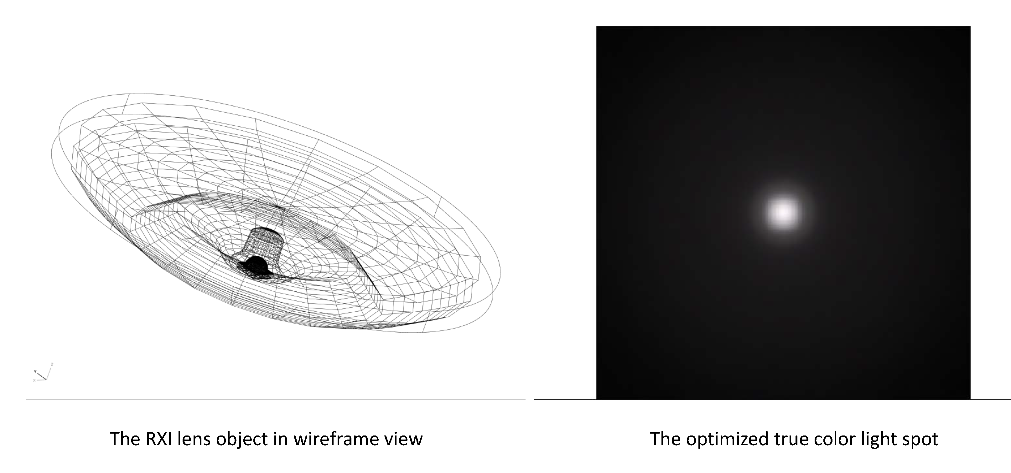
3. RXI lens designed with UDO in Zemax
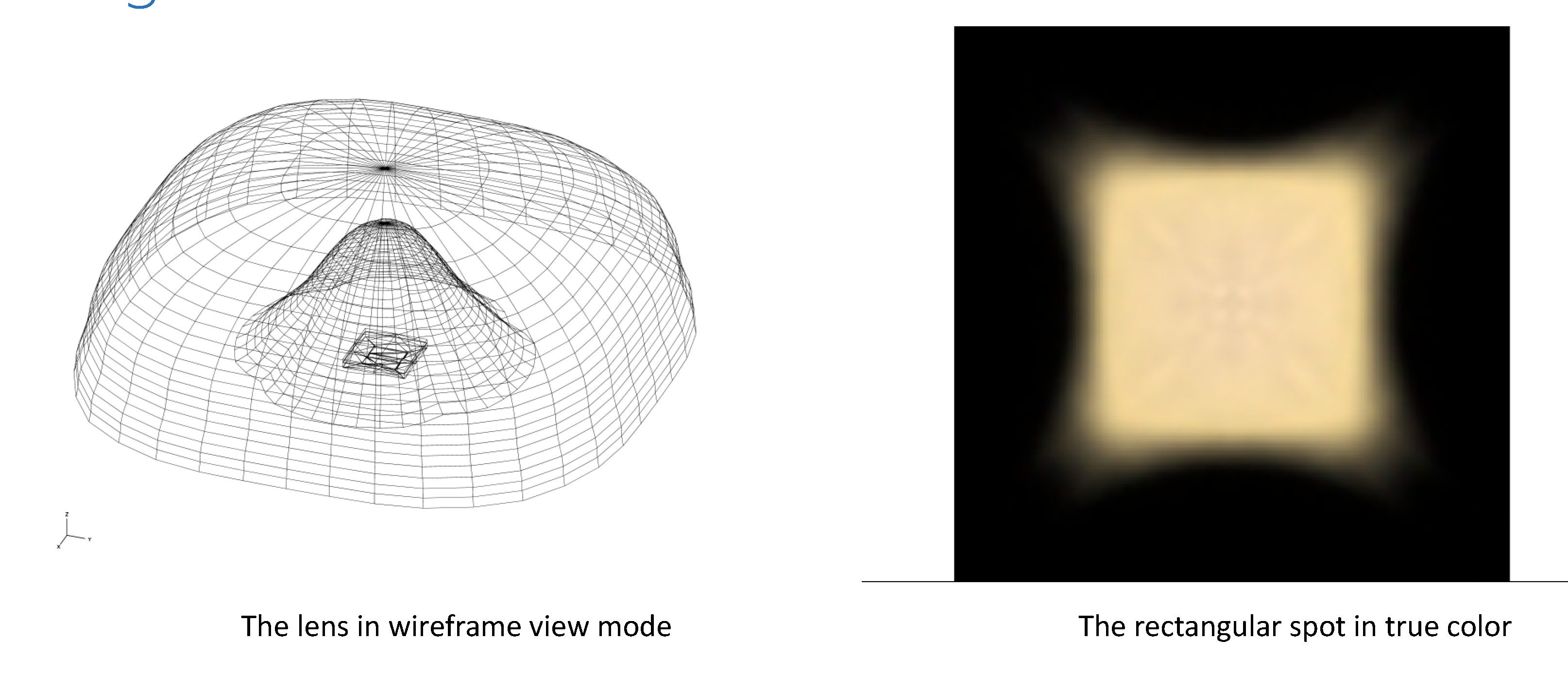
4. 130 degree angle uniform rectangle spot lens designed with UDO in Zemax
5. Type III streetlight lens designed with UDO in Zemax
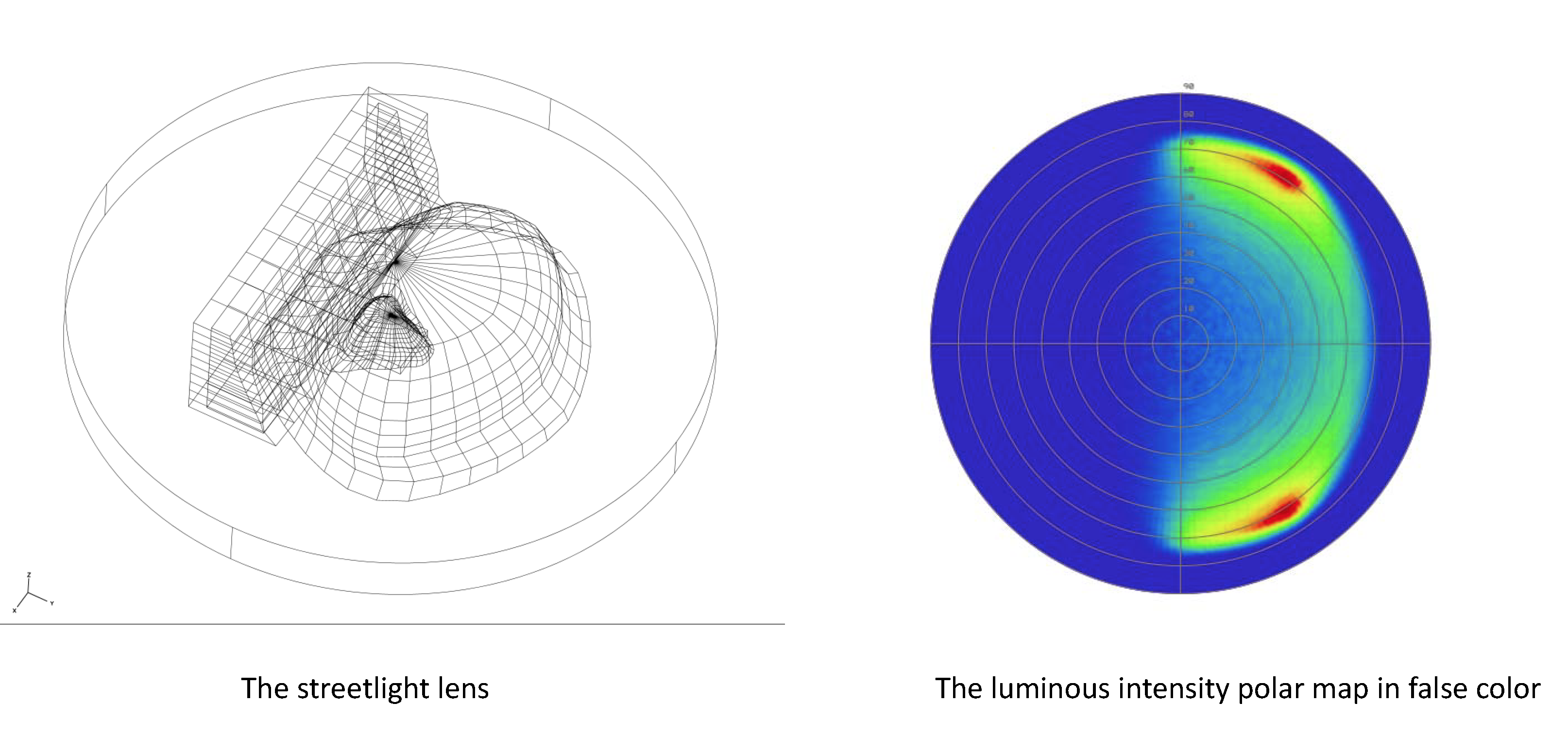
6. Type III streetlight lens designed with UDO in Zemax
7. Round Fresnel lens with a freeform curved shape of the tooth base
Using User-Defined Object, Macros, and User Defined surface greatly expand Zemax capabilities. And with the use of User-defined sources, scatter functions, and coatings Zemax is the most powerful and flexible optical design software in the world


 .
. , where
 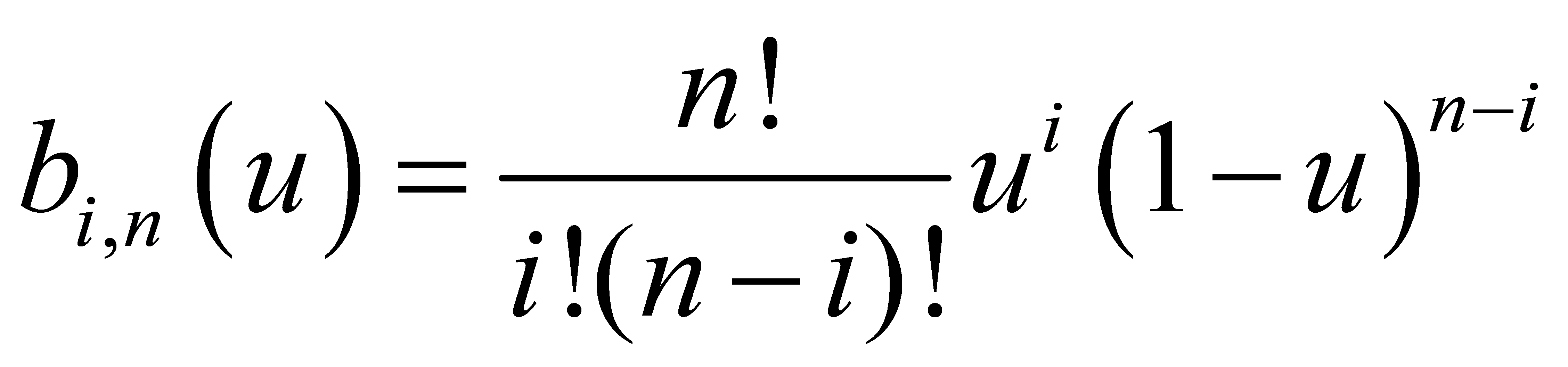 ,
,